Here I will go into detail about some of the technical stuff I used to make my LEDdress
I will talk about:
- Developing the circuit
- Developing the code
- Connecting the programmer to the Lilypad Arduino
- Connecting a battery to the Lilypad
Developing the circuit
Ingredients:
- An Arduino Lilypad
- Lilypad wearable LEDs
- One roll of conductive thread (not the yarn)
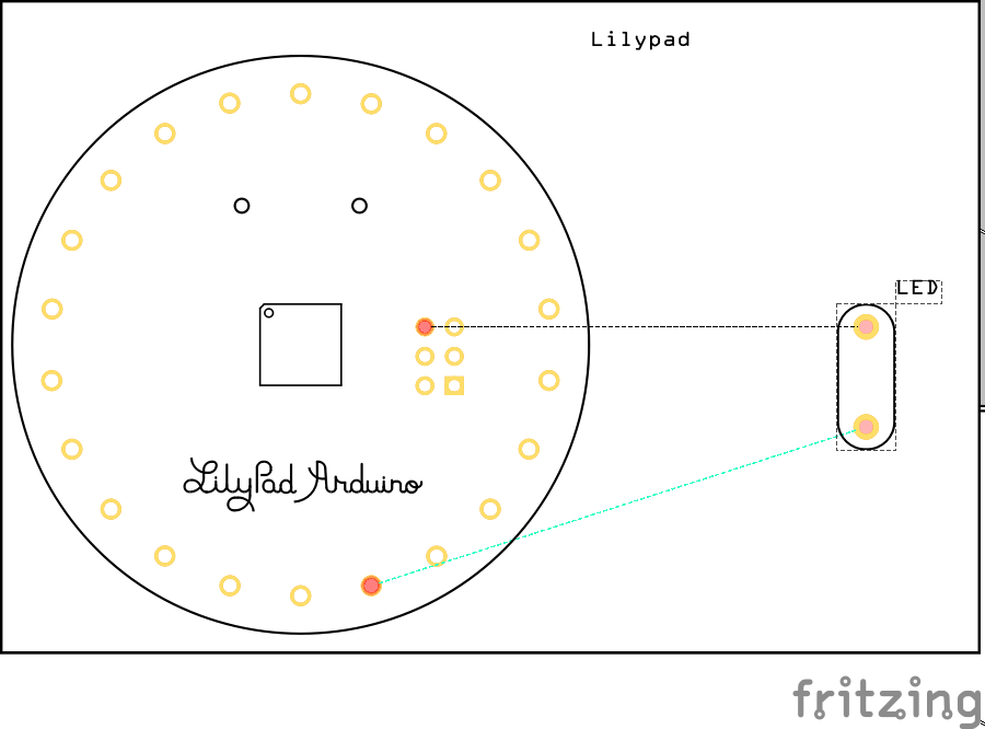
When making a circuit, power must always go from a plus-pin to a minus/ground. The output-pins of the Lilypad are plus-pins, they “give” power. Power must also be able to go “away” again, to complete the circle. The way to let the power flow away, is to send it to the minus-pin on the Lilypad.
Now, of course, this circuit doesn’t do anything, because there’s nothing connected to it. However, when a LED is placed in between, the LED would shine when the output-pin would send power through it.
Please note that the power must go “in” the plus side of the LED, and must “leave” from the minus side, so the circuit would be a complete circle again.
From here, multiple LEDs can be connected to one pin, or multiple LEDs can be connected to multiple pins. All the LEDs connected to the same pin will react the same at the same time. LEDs connected to different pins can react separately from each other (depending on your code, of course).
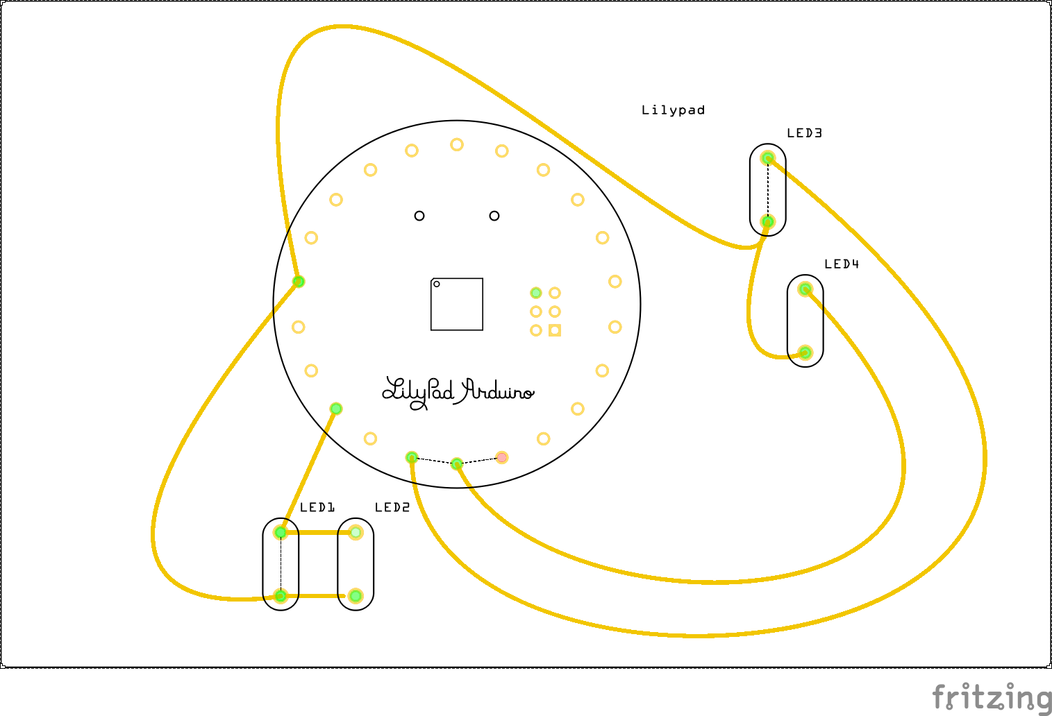
Here, the LEDs in the top half of the picture (LED3 and LED4) could react separately from each other. The LED1 and LED2 are connected to the same output and will react together.
All wires on the minus side (in the picture, the lower side) of the LEDs go to the GND pin on the Lilypad. They can use other minus-wires for that, they don’t have to do that on their own.
Keep in mind that, if wires cross they could short circuit, and nothing would work (or even overheat and die).
All Lilypads have different kinds of pins, as does the Lilypad Main board which I’ve used. Some of the pins are input-pins, which I won’t talk about because they’re not needed for this project. The output-pins are “normal” digital pins or are “PWM” digital pins.
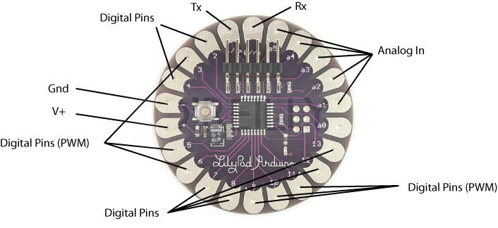
With “normal” digital pins, the LEDs can either be on (at full brightness), or off. With the PWM digital pins, the LED-brightness can differ between a value of 0-225, which makes them more interesting to program. For example, they can fade in- and out, like in my dress. PWM stands for Pulse Width Modulation, and theres a nice introduction to it over on the arduino site.
Its good to keep in mind which pins do what when attaching the LEDs.
Here’s an overview of the output-pins:
- Pin 2 – “normal” digital pin
- Pin 3 – “PWM” digital pin
- Pin 4 – “normal” digital pin
- Pin 5 – “PWM” digital pin
- Pin 6 – “PWM” digital pin
- Pin 7 – “normal” digital pin
- Pin 8 – “normal” digital pin
- Pin 9 – “PWM” digital pin
- Pin 10 – “PWM” digital pin
- Pin 11 – “PWM” digital pin
- Pin 12 – “normal” digital pin
- Pin 13 – “normal” digital pin
Also note that pin 2, 3 and 4 are on the other side of the minus pin. This can be important when you choose the placement of your Lilypad.
Eventually, my schematic looks like this:
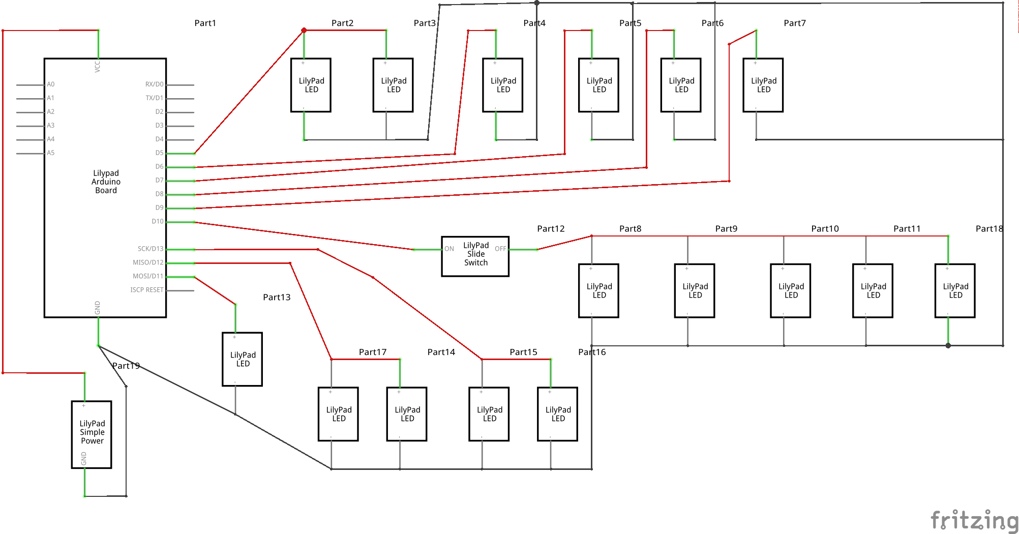
When sewing the LEDs on to my dress, I did not keep in mind that some of the pins were normal pins and other were PWM pins, this confused me a lot when I tried to program them all as PWM pins.
I also added more LEDs later on in the process, that’s why some pins have multiple LEDs connected to them and others only have one.
The minus poles of the LEDs don’t have to be connected separately to the ground (GND) pin of the Lilypad, so I just connected them via the shortest way I could find.
Developing the code
Ingredients:
- A laptop
- The Arduino IDE (“Integrated Development Environment”)
- To make it easier on yourself, the earlier made circuit, or a smaller test-circuit
Because the dress is flexible and the LEDs go all around, I thought it would be easier to have a small test-circuit to see the effect I made in to the LEDs. I made the circuit from an Arduino Uno and four LEDs. Once my code worked on four output-pins, I expanded it to the eight pins I use on the Lilypad.

As said before, I didn’t really pay attention when sewing the LEDs to their pins, and so I had used all kinds of pins for the LEDs. This confused me a lot when I tried to let all the LEDs fade in- and out, which they wouldn’t do. After figuring out some of the pins could only do on/off (the normal pins), and others could fade the LEDs (the PWM pins), I decided that the LEDs on the normal pins would always be on, and the LEDs on the PWM pins would always glow half-bright. They would then randomly fade into full brightness, before fading back to the half-brightness again.
Arduino code exists in functions. The functions are ‘parts’ of the full program, working on their own.
All code will be run from top to bottom (so, when I first say “turn the LED on” in the code, and after that “the LED = pin 5” it wouldn’t work, because when the LED gets turned on, it doesn’t know which pin the LED is).
There’s also comments in the code, you can recognize them by the “//” in front of them. The Arduino won’t do anything with this text, as its just for the humans reading it. For example, I used comments as a reminder to myself which LEDs were where.
A micro controller (tiny computer, like the Arduino Lilypad) works by looping the same thing over and over again. By doing this very fast, to us simple humans it looks like its doing something continuously.
My Arduino code starts with declaring the variables which all the functions should be able to access. After this the function ‘loop’ will turn all the LEDs on (and again, because it does this very fast, it will look like the LEDs are always shining). Then, while the LEDs are on, it picks a number between 0 and 5 at random. This number will correspond with a PWM-LED. The LED(s) on this pin will then slowly fade to full brightness and fading back again to their starting point. I put in a waiting time so I wouldn’t look like a disco ball. Once this is all done, it will start again with the same loop.
I’ve uploaded my code to Github so you can download it, use it and even make it better. You can, of course, also write your own code.
Connecting the programmer to the Lilypad Arduino
Ingredients:
- Arduino Lilypad
- A programmer/FDTI
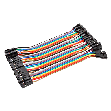
- Female-female (both have to have a hole, not a stick) jumper wires or dupont wires
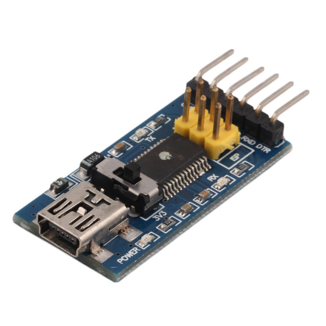
This is the programmer I got, it looks like the picture on the left.
The pins (those pointy things at the right side) of the programmer need to be connected to the Arduino. Do this without soldering, jumper/dupont wires (picture on the right) are used.
 |
 |
|---|
They need to be connected in the right order of course. Every pin on the programmer has a different function, as does every pin on the Arduino. Luckily, the schematics of both the programmer and the Lilypad Arduino are easily found online.
From top to bottom (on the picture below), the pins on the programmer are:
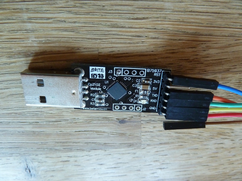
- RST – reset
- 3V – 3 volt
- 5V – 5 volt
- TXD – transmit data
- RXD – receive data
- GND – ground
These pins have to be connected to the Lilypad in the right order. Unfortunately, my Lilypad did not have the functions written down on it. In order to figure out which pins were what, I looked up a schematic.

This means that, from top to bottom (on the picture below), the pins on the Lilypad are:
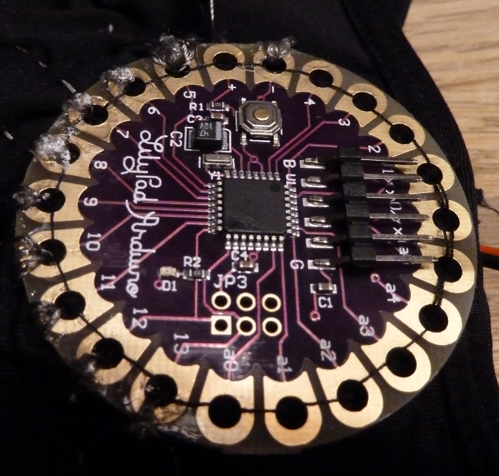
- GND – ground
- GND – ground
- PWR – power
- RXD – receive data
- TXD – transmit data
- DTR – data terminal ready
If we want to be able to transmit data from the programmer to the Lilypad, the pins have to be connected in the following order:
- From the programmer RST to the Lilypad DTR
As told before, a micro controller works by looping the same thing over and over again. However, when new code is uploaded to the Lilypad, it needs to stop the loop. By sending data to the RST pin, the programmer can tell the Lilypad when to stop (reset itself) and start receiving the new code. - We don’t use the 3V pin on the programmer, because we use the 5V one
- From the programmer 5V to the Lilypad PWR
This is where the Lilypad gets its power from, without it nothing works. - From the programmer TXD to the Lilypad RXD
The programmer will transmit data onto the Lilypad. The Lilypad thus must receive this data. Without this pin, the programmer and Lilypad can’t talk to each other. - From the programmer RXD to the Lilypad TXD
The Lilypad also wants to talk back to the programmer, in this case transmitted data from the Lilypad must be received by the programmer, again without this pin connected, the programmer and Lilypad can’t hear each other. - From the programmer GND to the Lilypad GND
In order to finish our power circuit, the power needs to go “away” again. The ground-pin, or minus, will make sure this happens.
In my case, uploading the code didn’t work at first.
My programmer was ordered from China, and sometimes the TXD and the RXD get mixed up in the cheaper electronics. The first thing I tried was to switch these wires (so, programmer TXD -> Lilypad TXD and programmer RXD -> Lilypad RXD). This wasn’t the fix.
Another thing that happens sometimes is when the programmer doesn’t reset the Lilypad via the pin. The Lilypad can be reset manually via the “reset” button on the board. The second thing I tried was to push this button on the Lilypad before I uploaded my code. Once pushed, the Lilypad would reset itself, flash the LEDs 3x, and then run the uploaded code. If I’d upload the code during the three flashes, the timing would be right and my code would upload.
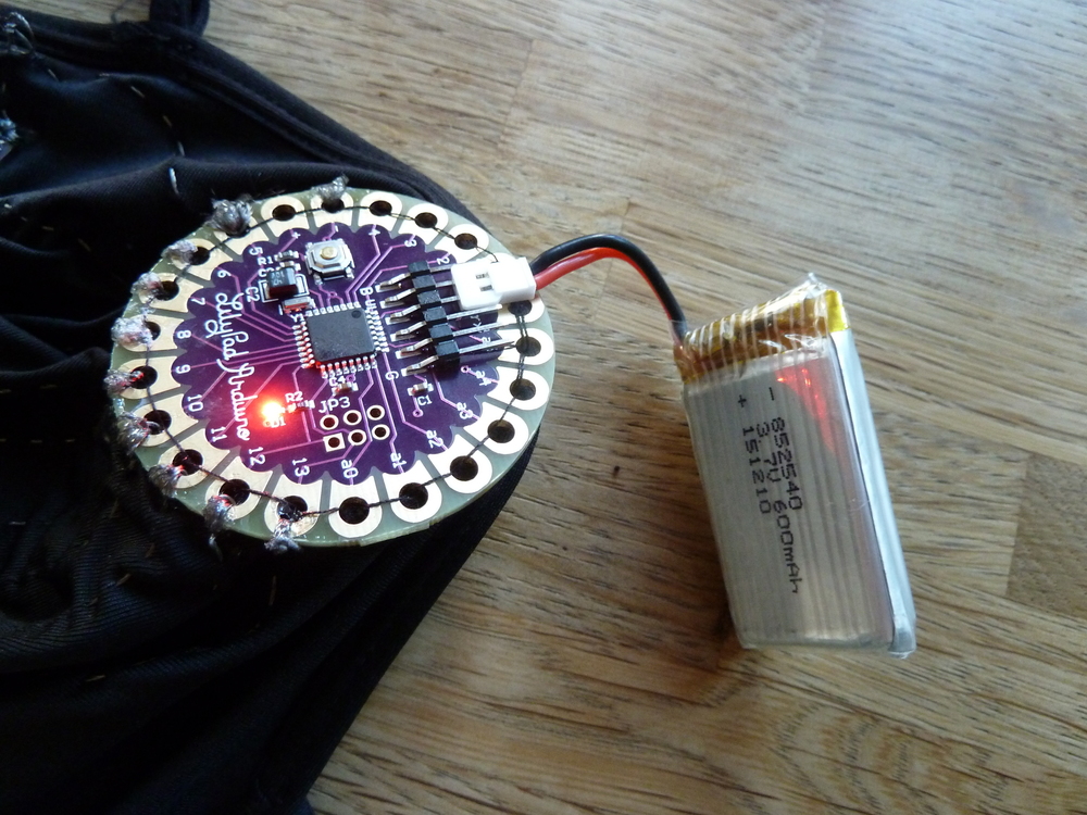
Connecting a battery to the Lilypad
Ingredients:
This was an easy one. The battery is 3.7V, and the Lilypad can handle anything between 2.2 and 5V, so it couldn’t overpower the Lilypad.
The red wire on a battery is always the power, and the black wire is always the ground. The battery already had a connector attached to it (that white plastic thing) and I could just connect the wires via the connector to the right pins of the Lilypad.